Lesson 8 - Subroutines


We have now covered many key areas of programming the Arduino and have used a variety of techniques to write a selection of programs. In this lesson, we will be learning a new technique when programming, called Subroutines.


What is a subroutine?

A subroutine can also be known as a function, when programming C language. A subroutine is often used for programming efficiency, to avoid repeating lines of code numerous times. This can be handy when writing complex programs on the Arduino. Below is a template showing the format as to how a subroutine function will look like in the IDE.


There are two different types of subroutines we can use with the Arduino. The one shown above is a standard function which simply runs a set of instructions, when called for. However, if the subroutine has specific data which we may want to change at different points of the main program, we can use variables names which must be declared in the subroutine and the value must be stated when the subroutine is called for. In theory, the Arduino takes the data from the point where the function is called from and then plugs that data to each point where the variable is used within the function. You can see this in the IDE example below:


Program Requirements

The program requirements of this program will be progressing on from Lesson 4 (Conditional Statements).

1. Blink an LED 10 times at 100 millisecond intervals

2. After 10 blinks at this time interval has been achieved, slow the LED blink time down to half a second for another 10 blinks.

3. Once a total of 20 LED blinks have been achieved, turn the LED off completely.

4. The total blink count must be displayed to the MFS 4x7 segment display.

5. Code efficiency will be taken into consideration in this program and therefore instruction sets must not be repeated.


Coding

To begin our program, we will first include the required libraries. For this sketch we need to use the 4x7 segment display, meaning we need to add the multi functional shield library as well as the timer one library. We also have two global variables which we will declare in the global scope, one being the LED pin and the other being our counter, which will store the blink count.


In the setup, configure the pin mode for the LED as an output and then initialise both the Timer and MFS libraries (as shown in the previous lesson).


Before we move on to the main loop section, we will ignore this for now and at the bottom of our sketch, we will create a subroutine. This is the subroutine we will call for when we need to blink the LED and we will include instructions to count the blinks and to display them to the 4x7 segment display. The way in which we will be creating this subroutine is as follows:


void Blink(int t){ //add code }


You can see that within the first set of parenthesis, we have declared a variable integer 't'. This is a variable integer which must be given a value in the loop function, when this subroutine is called. The reason we need this variable in our function will be more clear in a moment.


Within the curly parenthesis, we will write the set of instructions to digitally turn the LED on and off, using the increment function, we will count each blink and then to display the value we will use MFS.write. However, the delay instruction we use to time the intervals between each blink will include the variable integer 't'. This allows us to now call for the subroutine at different stages of our main loop, but enter our desired blink intervals.


delay(t);


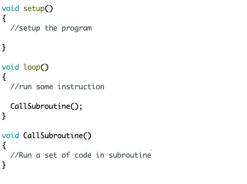
Now that the Blink subroutine function is complete, we can go back to completing the loop section of our program. Looking at the program requirements, we can pick out three key points:


1 - If the blink count is less than 10, we need to blink the LED at 100 millisecond intervals:

if (Count < 10) {

Blink(100);

}


2 - But, if the blink count is greater than 10 but less than 20, the LED must blink at 500 milliseconds:

else if (Count < 20) {

Blink(500);

}


3 - Once a total of 20 blinks have been achieved, turn the LED off completely:

else {

digitalWrite(LED, HIGH);

}


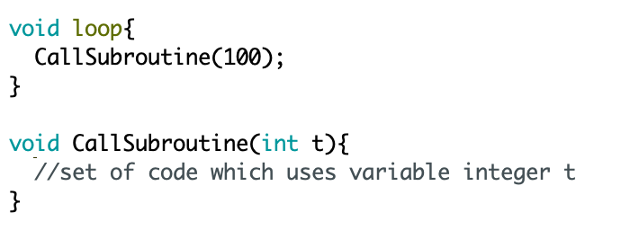
We have now completed the code and you can use the source code to test on you own boards. You can see how we have used the subroutine, conditional statements and the MFS 4x7 segment display. This function is great for code efficiency and allows us to perform an operation with a shorter program, rather than repeating instruction sets.


Source Code


We recommend copying the source code to the IDE


Code


By Zaqyas Mahmood, Electronics Engineer